|
|
 |
|
|
* Production Sizes and Tolerances in accordance with DIN 8077 / December 1997:
|
|
|
|
|
External Diameter dmm
|
Tolerance limit mm
|
Wall thickness S mm
|
Thickness tolerance mm
|
Approximate unit weight kg/m
|
|
16
|
+ 0.3
|
2.7
|
+ 0.5
|
0.110
|
|
20
|
+ 0.3
|
3.4
|
+ 0.6
|
0.172
|
|
25
|
+ 0.3
|
4.2
|
+ 0.7
|
0.266
|
|
32
|
+ 0.3
|
5.4
|
+ 0.8
|
0.434
|
|
40
|
+ 0.4
|
6.7
|
+ 0.9
|
0.671
|
|
50
|
+ 0.5
|
8.3
|
+ 1.1
|
1.040
|
|
63
|
+ 0.6
|
10.5
|
+ 1.3
|
1.650
|
|
75
|
+ 0.7
|
12.5
|
+ 1.5
|
2.340
|
|
90
|
+ 0.9
|
15.0
|
+ 1.7
|
3.360
|
|
110
|
+ 0.9
|
18.3
|
+ 2.1
|
5.010
|
|
125
|
+ 1.2
|
20.8
|
+ 2.3
|
6.470
|
|
|
|
|
* Physical Properties:
|
|
|
|
|
Property
|
Test Method
|
Unit
|
Value
|
|
Density at 23°C
|
ISOR 1183
|
g/cm3
|
0.90
|
|
Melt flow index
|
|
|
|
|
MFI 190°C/5 kg
|
ASTM D 1238
|
g/10dak.
|
0.70
|
|
MFI230°C/2.16kg
|
ISOR 1133
|
g/I0dak.
|
0,2-0,45
|
|
MFI 230°C/5 kg
|
DIN 53 735
|
g/10dak.
|
0,6+1,2
|
|
Fusion point
|
|
°C
|
146
|
|
|
|
|
* Thermal Properties:
|
|
|
|
|
Property
|
Test Method
|
Unit
|
Value
|
|
Thermal Conductivity at 23°C
|
DIN 52612
|
W/m.K
|
0.23
|
|
Specific heat at 23°C
|
C
|
Kj/kg.K
|
1.73
|
|
Coefficient of linear
thermal expansion
|
DIN 53 752
|
K-1
|
1. 5-1. 8x1 0-4
|
|
Under weight
deformation temperature 1.8N/mm2
0.45 N/mm2
|
ASTM D 648
ISO 75
DIN 53 461
|
°C
°C
|
44
72
|
|
Breaking temperature
|
ASTM D 746
|
°C
|
-13
|
|
VICAT softening point
(1 kg.)
(5 kg.)
|
ASTMD 1525
ISO 306
DIN 53 460
|
°C
°C
|
130
60
|
|
|
|
|
* Mechanical Properties:
|
|
|
|
|
Properties
|
Test Method
|
Unit
|
Value
|
|
Strength at flow limit at 23°C
Speed of pulling: 50 mm/minute
100 mm/minute
|
|
N/mm2
N/mm2
|
22
23
|
|
Extension at flow limit at 23 °C
Speed of pulling: 50 mm/minute
100 mm/minute
|
ISO R 527
(Sample No 1)
|
%
%
|
17
18
|
|
Break strength at 23°C
Speed of pulling: 50 mm/minute
100 mm/minute
|
DIN 53455 (Sample No 1)
|
N/mm2
N/mm2
|
35
34
|
|
Extension of break out at 23°C
Speed of pulling: 50 mm/minute
100 mm/minute
|
|
%
%
|
>500
>500
|
|
Elasticity module at 23°C
|
ASTM D 790
|
N/mm2
|
670
|
|
Bend module at 23°C
|
DIN 53 447
|
N/mm2
|
185
|
|
Shore D hardness
|
ASTM D 740 ISO R 868,
DIN 53 505
|
|
65
|
|
IZO D impact strength
(notched)at 23°C
at 0°C
|
ISO R 180
ASTM D 256
|
j/m2
j/m2
|
105
30
|
|
CHARPY impact strength
(notched)at 23°C
at 0°C
|
DIN 53 453 ISOR 179
|
kj/m2
kj/m2
|
15
35
|
|
CHARPY impact strength
(unnotched)at 23°C
at 0°C
|
DIN 53 453
ISO R 179
|
kj/m2
kj/m2
|
No break
|
|
Impact strength, at 0°C
|
DIN 8078
Part 2
|
|
No break
|
|
|
|
|
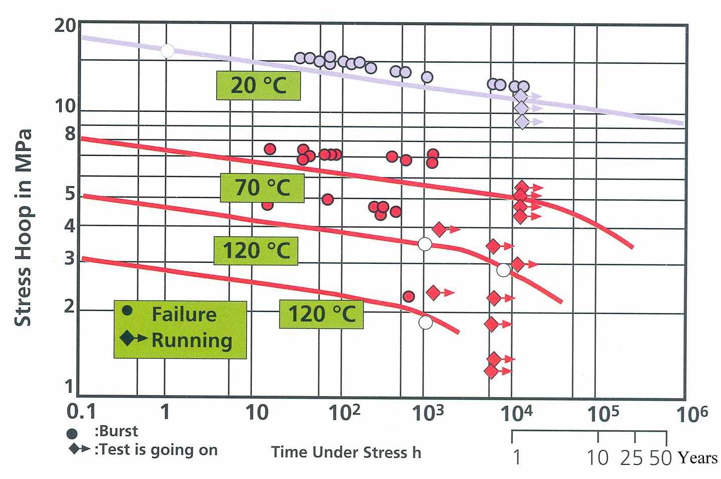
* Operating life time in accordance with DIN 8078 / April 1996:
|
|
|
|
|
Temperature
(°C)
|
Life
(y)
|
Design stress
(MPa)
|
|
20
|
50
|
9.5
|
|
40
|
50
|
6.8
|
|
60
|
50
|
4.7
|
|
70
|
50
|
3.2
|
|
80
|
25
|
2.5
|
|
95
|
5
|
1.85
|
|
|
|
|
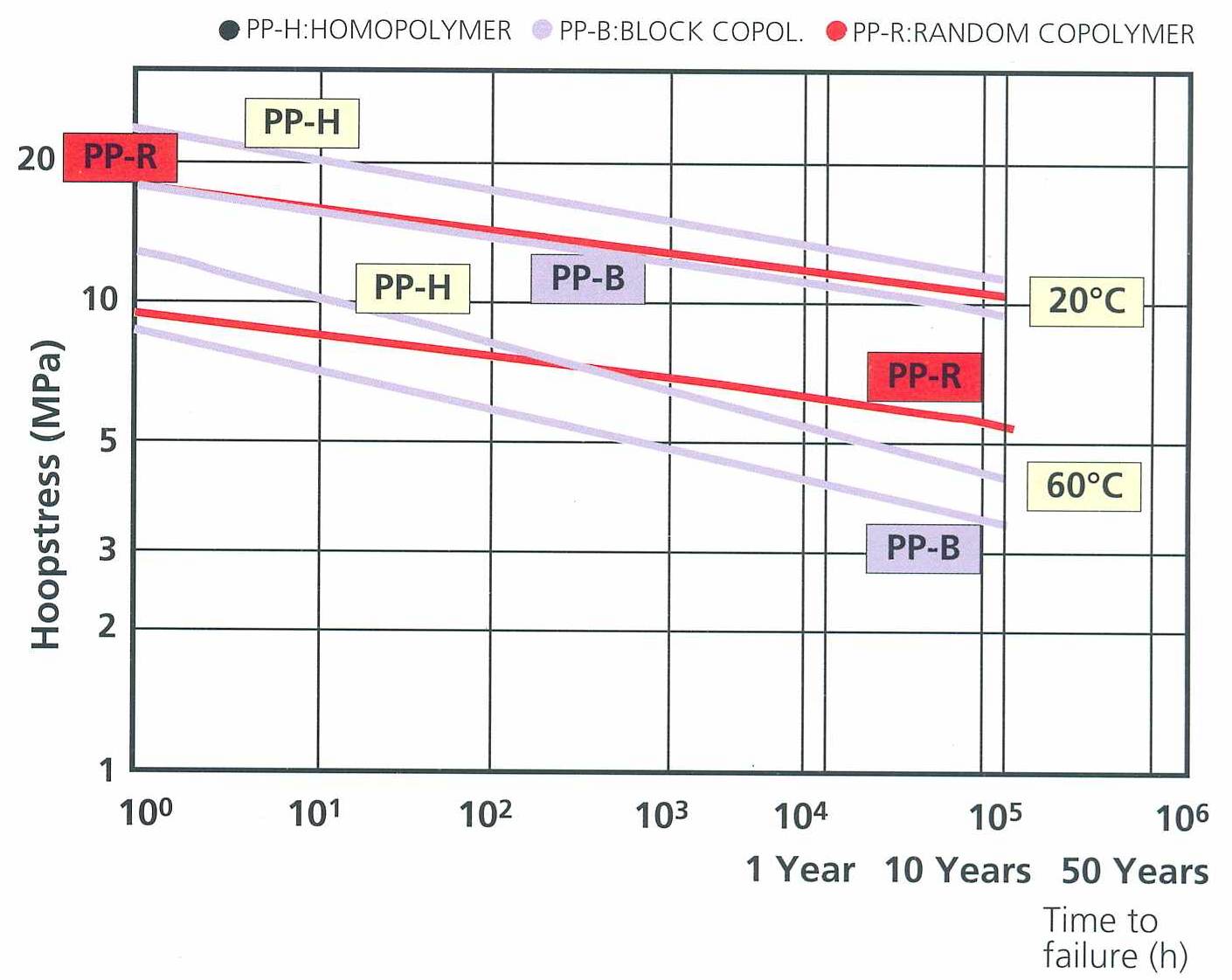
* Break Strength for PP-R Pipes according to DIN 8078:
|
|
|
|
© copyright 2017: almanit sanitary gmbh, Hamburg, Germany
All rights reserved. Reproduction in whole or in part without the written permission of the copyright owner is prohibited. |
|